You are using an out of date browser. It may not display this or other websites correctly.
You should upgrade or use an alternative browser.
You should upgrade or use an alternative browser.
News The Space Shuttle for Flightgear 3.6
- Thread starter Thorsten
- Start date


Thorsten
Active member
- Joined
- Dec 7, 2013
- Messages
- 785
- Reaction score
- 56
- Points
- 43
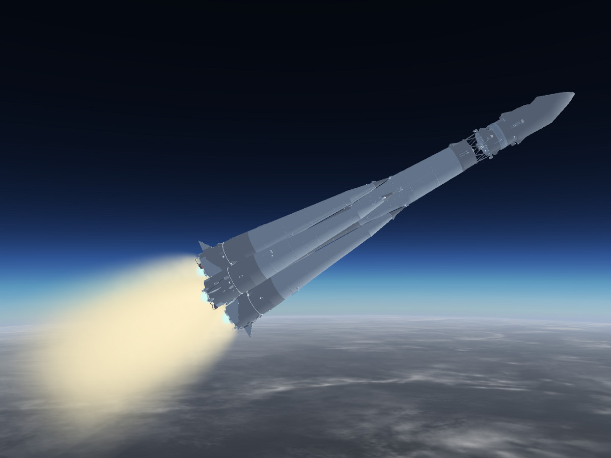
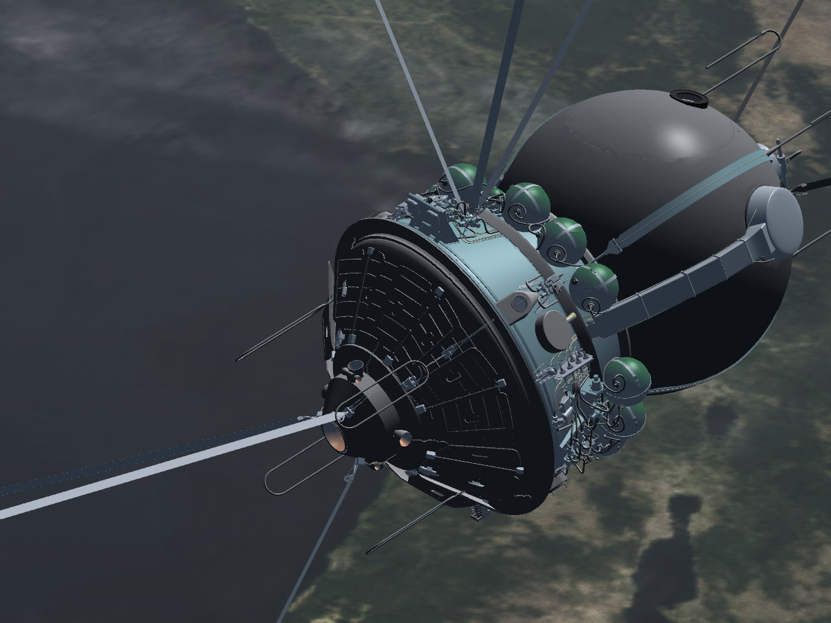
Since I was just doing maintenance on it, let me take the opportunity to get a bit off-topic and introduce Flightgear's third space-capable ride after the X-15 and the Shuttle - Vostok.
The rocket is implemented from launch to touchdown, but it's aerodynamically not as interesting as the Shuttle. Control is on manual during all phases of the flight (well, during entry you just sit and black out when the g-force is ramping up), but steering it into orbit, dropping the various stages on the way and navigating with a very simplistic set of analogue instruments is fun.
The author is a fan of lavish 3d modeling, so the TDU has an insane amount of detail with even wires modeled - dependent on your graphics card performance, that's a good or a bad thing. I don't know how faithful it is to the original (I don't know if performance data of a Vostok rocket is even in public domain...), but there's not so much margin for error in reaching orbit, so the gross performance seems plausible,
Here's a few impressions from a test flight:
Pitching down after coming out of the atmosphere, first stage boosters and second stage burning:
Only second stage left, protective cover blown off:
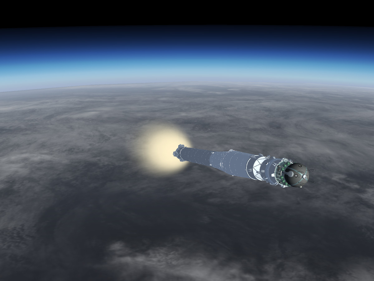
Third stage ignition, slow crawl to orbital speed:
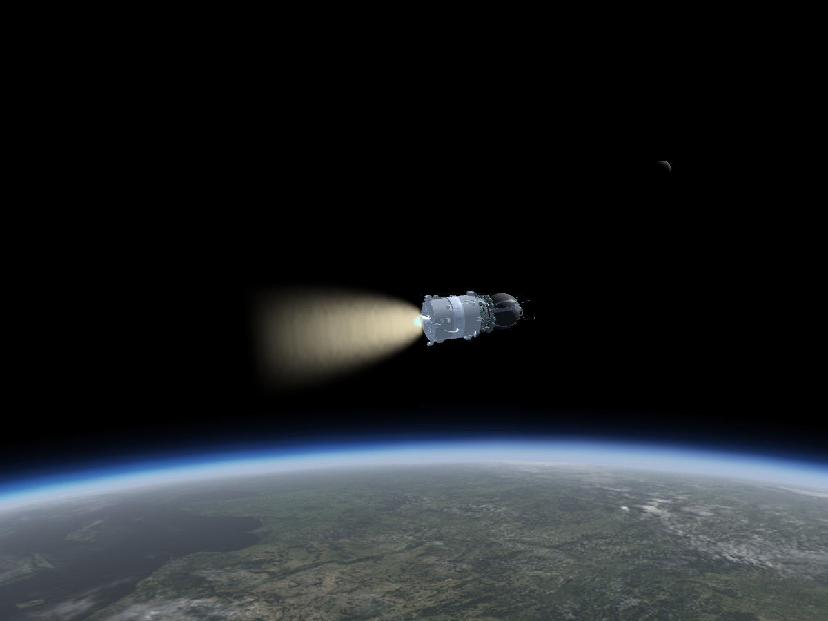
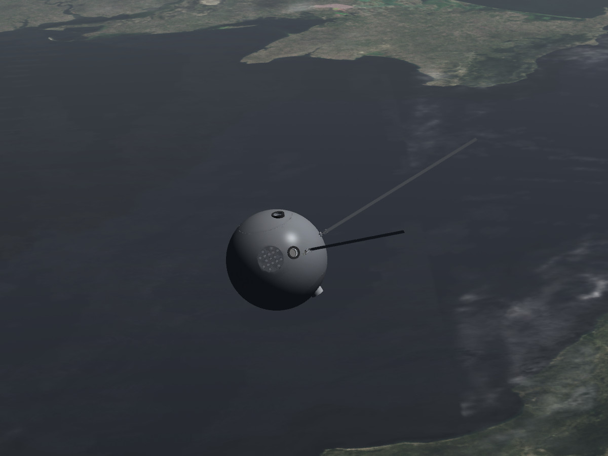
The TDU in orbit:
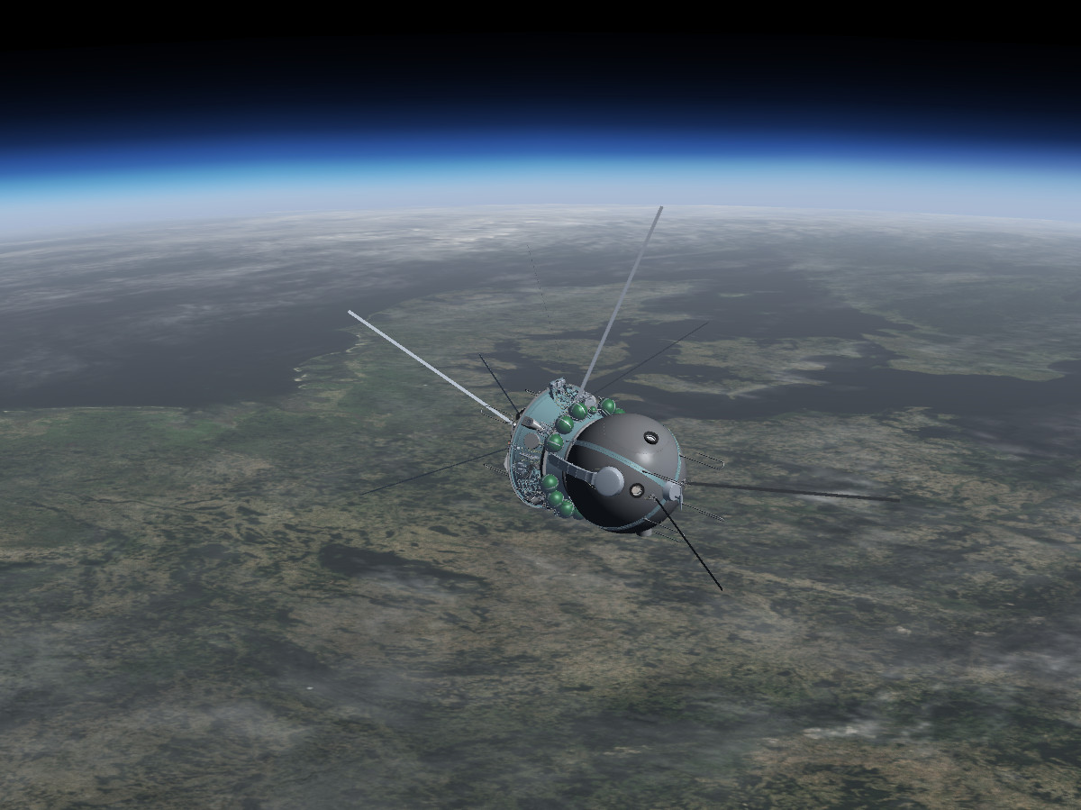
Detail view of the TDU :
Support module dropped, ready to enter the atmosphere (no piloting from this point, you're just along for the ride and may expect a crushing g-load):
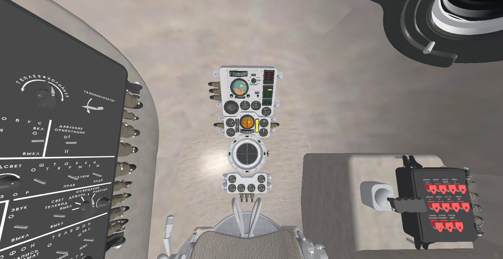
Here's a view of the interior (with the right panel added to provide manual control of stage management which isn't there in reality - the rest of the instrumentation is as far as I know faithful to the original):
The rocket is implemented from launch to touchdown, but it's aerodynamically not as interesting as the Shuttle. Control is on manual during all phases of the flight (well, during entry you just sit and black out when the g-force is ramping up), but steering it into orbit, dropping the various stages on the way and navigating with a very simplistic set of analogue instruments is fun.
The author is a fan of lavish 3d modeling, so the TDU has an insane amount of detail with even wires modeled - dependent on your graphics card performance, that's a good or a bad thing. I don't know how faithful it is to the original (I don't know if performance data of a Vostok rocket is even in public domain...), but there's not so much margin for error in reaching orbit, so the gross performance seems plausible,
Here's a few impressions from a test flight:
Pitching down after coming out of the atmosphere, first stage boosters and second stage burning:
Only second stage left, protective cover blown off:
Third stage ignition, slow crawl to orbital speed:
The TDU in orbit:
Detail view of the TDU :
Support module dropped, ready to enter the atmosphere (no piloting from this point, you're just along for the ride and may expect a crushing g-load):
Here's a view of the interior (with the right panel added to provide manual control of stage management which isn't there in reality - the rest of the instrumentation is as far as I know faithful to the original):
Thorsten
Active member
- Joined
- Dec 7, 2013
- Messages
- 785
- Reaction score
- 56
- Points
- 43
The FG team is happy to announce that we've just prepared the 2016-2 'Barcelona' release of FG.
This contains the latest versions of Vostok and the Shuttle as described in this thread (along with many things that are not so relevant for spaceflight, such as the birds being disturbed by this morning launch):

The files can be found here:
https://sourceforge.net/projects/flightgear/files/release-2016.2/
an official release announcement is soon to follow.
This contains the latest versions of Vostok and the Shuttle as described in this thread (along with many things that are not so relevant for spaceflight, such as the birds being disturbed by this morning launch):
The files can be found here:
https://sourceforge.net/projects/flightgear/files/release-2016.2/
an official release announcement is soon to follow.
Thorsten
Active member
- Joined
- Dec 7, 2013
- Messages
- 785
- Reaction score
- 56
- Points
- 43
Some behind the scenes development which took a while - the orbital targeting computer is gradually coming into shape.
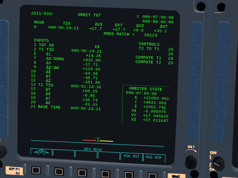
It's implemented as a Hohmann++ function right now - it starts with analytic expressions for the transfer orbit as a first guess, then does a multi-parameter fit of a numerical trajectory prediction using the actual non-spherical gravity expressions for the serious targeting, taking into account that you might have started from an eccentric orbit and correcting small inclination offsets.
It still has a few quirks characteristic of non-linear multi-parameter fits (someone once said they resemble an art more than science... there's something to that...) - the fit takes longer than it should sometimes because the solution oscillates around the minimum for a while,...that kind of thing.
I wasted a lot of time trying shortcuts with analytic expressions for 2-body orbital elements for pointmass gravity, but it turns out you easily incur errors of 50 km and more in the targeting that way, so it all had to be done numerically in the end. But otherwise it's pretty neat - you select the target ID, run the targeting code, resume to MNVR, load the burn solution and set the timers and watch it all happen... sadly, users probably will never appreciate how non-trivial it all is...
- Joined
- Oct 26, 2011
- Messages
- 1,231
- Reaction score
- 619
- Points
- 128
It's implemented as a Hohmann++ function right now - it starts with analytic expressions for the transfer orbit as a first guess, then does a multi-parameter fit of a numerical trajectory prediction using the actual non-spherical gravity expressions for the serious targeting, taking into account that you might have started from an eccentric orbit and correcting small inclination offsets.
So it doesn't solve Lambert's Problem? Or how exactly is the initial, analytical guess calculated? Maybe you have made the numerical calculations more complicated than the Shuttle computer would have been able to handle. :lol:
Also, have you already implemented the search for TIG with an elevation angle input? That was usually done for a typical MC2 maneuver of an ISS rendezvous.
Thorsten
Active member
- Joined
- Dec 7, 2013
- Messages
- 785
- Reaction score
- 56
- Points
- 43
Or how exactly is the initial, analytical guess calculated?
* get the mean angular motion in deg/s for both Shuttle and target orbits
* get the required angle for a Hohmann transfer from Shuttle to target orbit
* compute when, given the relative angular motion, that angle is reached
-> use the angle, the resulting TIG and the Hohmann Delta v's as first guess
Maybe you have made the numerical calculations more complicated than the Shuttle computer would have been able to handle.
Possibly... the numerical predictor solves the equations of motions for the non-spherical gravity field in time-steps of 0.05 seconds - and checks ever 100 steps (5 seconds) whether a target condition is reached.
The burn is currently still an instantaneous Dv addition, though it can be made finite-duration.
Possibly the largest uncertainty in practice however is that the avionics (by design) doesn't know the exact mass of the Shuttle at every time instant and doesn't control burn duration with infinite precision. Also, the prediction doesn't take into account exhaust vent forces or residual Delta-v picked up from RCS thruster attitude management.
Also, have you already implemented the search for TIG with an elevation angle input?
No. but now that I have a solver and a working fit routine, changing the conditions to which the fit runs is in comparison a much easier task.

Thorsten
Active member
- Joined
- Dec 7, 2013
- Messages
- 785
- Reaction score
- 56
- Points
- 43
Close-up on the ADI ball after applying cosmetics:

This really is a challenging instrument to code, but now it has all the correct distortions of the lines, the correct slant of the meridian labels everywhere (without distortions applied to the labels), minor ticks with correct projection, full three axis motion, can be driven by angles in any of the available coordinate systems (inertial, LVLH or REF) and changes the projection automagically, ...
It really runs on a simple real-time 3d rendering code - as a by-product, that could render arbitrary meshes from different perspectives, so it would deliver a wireframe of a landing site topology just as well.
If anyone is interested in the math, I'd be happy to share the algorithm.
Thorsten
Active member
- Joined
- Dec 7, 2013
- Messages
- 785
- Reaction score
- 56
- Points
- 43
Okay - so let''s try to keep it simple then.
The basic idea is to create all structures as 3d coordinates on a sphere, then project everything into 2d space dependent on vehicle attitude (aka your 'view vector') and post-process the resulting 2d data set and pass the final array to a drawing routine.
If we sit in the center of a sphere such that x forward, y right and z upward, the projection into 2d space is easy as long as we look forward:
* we test whether something has a negative x
-> if so, we drop the point because we can't see it, it's behind us
-> if not, we take the point with x set to zero and create a 2d point (xy)_2d = (y_3d, z_3d)
If we're not looking forward, we need to transform everything into the coordinate system where we do. So we start with a set of 3 base vectors (1,0,0), (0,1,0), (0,0,1) and do a Tait-Bryan rotation to get the base vector set for the current attitude:
(just look up the rotation matrix for the (yaw/pitch/roll) convention on Wikipedia, )
Now assume we dump ex', ey' and ez' into an array of vectors p_vecs - so we have the view_vec (along which we project) and x_proj and y_proj. If we have a sphere point in the original coordinates, we just dot it into each of the new base vectors to get the point into the rotated coordinates (and afterwards do the above flattening in the depth coordinate).
Afterwards we can clip in a circular area
The draw call for, say, a meridian then sets longitude to a value and varies latitude of the point, computes the 3d position based on (lat, lon, radius) in the original coordinates, transforms into the new coordinates and then does projection and clipping
and only once a point passes the depth test and the clipping, it is appended to the shape data array and passed onward to drawing.
So a call to draw_meridian returns an array of the projection of the meridian in 2d space dependent on the current vehicle attitude.
Many of these steps are what the graphics card does during the rasterizer stage between vertex shader and fragment shader processing (rotation into eye space, projection into screen space, view frustrum culling,...) which is why I mentioned it helps to know some 3d rendering.
The basic idea is to create all structures as 3d coordinates on a sphere, then project everything into 2d space dependent on vehicle attitude (aka your 'view vector') and post-process the resulting 2d data set and pass the final array to a drawing routine.
If we sit in the center of a sphere such that x forward, y right and z upward, the projection into 2d space is easy as long as we look forward:
* we test whether something has a negative x
-> if so, we drop the point because we can't see it, it's behind us
-> if not, we take the point with x set to zero and create a 2d point (xy)_2d = (y_3d, z_3d)
If we're not looking forward, we need to transform everything into the coordinate system where we do. So we start with a set of 3 base vectors (1,0,0), (0,1,0), (0,0,1) and do a Tait-Bryan rotation to get the base vector set for the current attitude:
Code:
var orientTaitBryan = func (v, h, p, r) {

var heading_rad = h * math.pi/180.0;
var pitch_rad = p * math.pi/180.0;
var roll_rad = r * math.pi/180.0;

var c1 = math.cos(heading_rad);
var s1 = math.sin(heading_rad);

var c2 = math.cos(pitch_rad);
var s2 = math.sin(pitch_rad);

var c3 = math.cos(roll_rad);
var s3 = math.sin(roll_rad);

var x = v[0];
var y = v[1];
var z = v[2];

var x1 = x * (c1 * c2) + y * (c1 * s2 * s3 - c3 * s1) + z * (-s1 * s3 - c1 * c3 * s2);
var y1 = x * (c2 * s1) + y * (c1 * c3 + s1 * s2 * s3) + z * (-c3 * s1 * s2 + c1 * s3);
var z1 = x * s2 + y * (-c2 * s3) + z * c2 * c3;

var out = [];

append(out, x1);
append(out, y1);
append(out, z1);

return out;
}
(just look up the rotation matrix for the (yaw/pitch/roll) convention on Wikipedia, )
Now assume we dump ex', ey' and ez' into an array of vectors p_vecs - so we have the view_vec (along which we project) and x_proj and y_proj. If we have a sphere point in the original coordinates, we just dot it into each of the new base vectors to get the point into the rotated coordinates (and afterwards do the above flattening in the depth coordinate).
Code:
var projection = func (point_coords, view_vec, x_proj, y_proj) {

var projected_point = [0.0, 0.0, 0.0];

projected_point[0] = SpaceShuttle.dot_product(point_coords, x_proj);
projected_point[1] = SpaceShuttle.dot_product(point_coords, y_proj);

var hemisphere = SpaceShuttle.dot_product(point_coords, view_vec);

if (hemisphere < -0.2)
	{projected_point[2] = -1;}
else if (hemisphere < 0.0)
	{projected_point[2] = 0;}
else
	{projected_point[2] = 1;}

return projected_point;

}
Afterwards we can clip in a circular area
Code:
var circle_clipping = func (projected_point, radius) {

var length = math.sqrt(projected_point[0] * projected_point[0] + projected_point[1] * projected_point[1]);

if (length > 1.2 * radius)
	{
	projected_point[2] = -1;
	}
else if (length > radius)
	{
	projected_point[2] = 0;
	}
return projected_point;

}
The draw call for, say, a meridian then sets longitude to a value and varies latitude of the point, computes the 3d position based on (lat, lon, radius) in the original coordinates, transforms into the new coordinates and then does projection and clipping
Code:
var draw_meridian = func (lon, npoints, p_vecs) {

var dlat = 170.0 / (npoints-1);
var lon_rad = lon * math.pi/180.0;


var shape_data = [];

for (var i = 0; i < npoints; i=i+1)
	{
	var lat_rad = (-85.0 + i * dlat) * math.pi/180.0;

	var x = math.sin(lon_rad) * math.cos(lat_rad);
	var y = math.cos(lon_rad) * math.cos(lat_rad);
	var z = math.sin(lat_rad);

	var projected_point = projection ([x,y,z], p_vecs[0], p_vecs[1], p_vecs[2]);
	projected_point = circle_clipping(projected_point, 0.75);


	if (projected_point[2] > -1)
		{append(shape_data, projected_point);}
	}

return shape_data;

}
and only once a point passes the depth test and the clipping, it is appended to the shape data array and passed onward to drawing.
So a call to draw_meridian returns an array of the projection of the meridian in 2d space dependent on the current vehicle attitude.
Many of these steps are what the graphics card does during the rasterizer stage between vertex shader and fragment shader processing (rotation into eye space, projection into screen space, view frustrum culling,...) which is why I mentioned it helps to know some 3d rendering.
Thorsten
Active member
- Joined
- Dec 7, 2013
- Messages
- 785
- Reaction score
- 56
- Points
- 43
And here's the PFD in ascent mode in (almost) full glory:

Pretty much all elements except X-Trk work for a nominal ascent (the changes for TAL and RTLS will still take a while). Error needles should be good to fly a proper ascent manually (haven't tried it, I have flown so many I don't really need them any more...).
It's fun watching the difference between earth-relative and inertial velocity vector bearing indicator disappear over time - it's sort of a rather visual illustration of what is happening in the transit from one coordinate system into the other.
Thorsten
Active member
- Joined
- Dec 7, 2013
- Messages
- 785
- Reaction score
- 56
- Points
- 43
In the last few days, I added Shuttle autopilots for entry and TAEM - so for the lazy ones, the Shuttle can now be flown without ever touching the stick for almost all mission phases - except final approach and touchdown, that you have to do yourself (just like in reality).
The entry AP is about as good as I am, i.e. it has some deviation around the optimal trajectory, but gets you into a workable TAEM solution. It can do some fancy stuff that looks very sickening (and is hard to do when flying manually) which is alpha modulation - changing AoA during entry by +- 3 degrees corresponds to an instantaneously change of drag by some 10%, which works much faster than changing drag by changing altitude and is used to dampen the oscillations around the guidance target. It also has a low energy mode in which low drag flight rules are used in case you're coming in long. Like the real thing, it does not know about structural limits, aka it will kill you if it decides we need more drag than the Shuttle can take in terms of g-forces - manual take-over is the required procedure.
The TAEM AP can do everything up to the final turn into the approach. It will do S-turns if it thinks we're high on energy and dynamically adapts if you down-mode to a different entry point or HAC procedure. It didn't always deliver me into the optimum approach, but reliably into a flyable approach (some 1000-2000 ft higher or lower). Real procedures are taking over by the time the Shuttle goes subsonic by the way - usually that's well before reaching the HAC - so don't complain if it ain't perfect!
Both APs are fully interfaced to the PFD, so even if you have pitch and/or yaw/roll down-moded to CSS, the error needles on the PFD will be meaningful and will deliver you into the APs preferred solutions if you manually follow them (personally, I find it easier to fly by the 'big picture' from ENTRY TRAJ and VERT SIT than to chase the needles, but to each his own...)
As a challenge, I've tested a complete TAL scenario from KSC to Zaragoza under automatic control, and it worked beautifully.
Happy flying!
---------- Post added at 06:36 PM ---------- Previous post was at 11:51 AM ----------
Some visuals of the new features...
Here's the new PFD in entry mode reflecting the guidance info from the autopilot as it intercepts the desired trajectory:

The view from the cockpit is a bit weird during entry - especially if alpha modulation also yanks the shuttle around:

Doesn't fit the theme, but a user decided to go through the trouble and encode night lights in the planet texture alpha channel, and by some GLSL magic I made it a bit more gritty and created a bit of color blends - so now the nightside of Earth looks like this (with a bit of aurora over the pole thrown in for good measure)

The entry AP is about as good as I am, i.e. it has some deviation around the optimal trajectory, but gets you into a workable TAEM solution. It can do some fancy stuff that looks very sickening (and is hard to do when flying manually) which is alpha modulation - changing AoA during entry by +- 3 degrees corresponds to an instantaneously change of drag by some 10%, which works much faster than changing drag by changing altitude and is used to dampen the oscillations around the guidance target. It also has a low energy mode in which low drag flight rules are used in case you're coming in long. Like the real thing, it does not know about structural limits, aka it will kill you if it decides we need more drag than the Shuttle can take in terms of g-forces - manual take-over is the required procedure.
The TAEM AP can do everything up to the final turn into the approach. It will do S-turns if it thinks we're high on energy and dynamically adapts if you down-mode to a different entry point or HAC procedure. It didn't always deliver me into the optimum approach, but reliably into a flyable approach (some 1000-2000 ft higher or lower). Real procedures are taking over by the time the Shuttle goes subsonic by the way - usually that's well before reaching the HAC - so don't complain if it ain't perfect!
Both APs are fully interfaced to the PFD, so even if you have pitch and/or yaw/roll down-moded to CSS, the error needles on the PFD will be meaningful and will deliver you into the APs preferred solutions if you manually follow them (personally, I find it easier to fly by the 'big picture' from ENTRY TRAJ and VERT SIT than to chase the needles, but to each his own...)
As a challenge, I've tested a complete TAL scenario from KSC to Zaragoza under automatic control, and it worked beautifully.
Happy flying!
---------- Post added at 06:36 PM ---------- Previous post was at 11:51 AM ----------
Some visuals of the new features...
Here's the new PFD in entry mode reflecting the guidance info from the autopilot as it intercepts the desired trajectory:
The view from the cockpit is a bit weird during entry - especially if alpha modulation also yanks the shuttle around:
Doesn't fit the theme, but a user decided to go through the trouble and encode night lights in the planet texture alpha channel, and by some GLSL magic I made it a bit more gritty and created a bit of color blends - so now the nightside of Earth looks like this (with a bit of aurora over the pole thrown in for good measure)
Thorsten
Active member
- Joined
- Dec 7, 2013
- Messages
- 785
- Reaction score
- 56
- Points
- 43
Big moment... after some sweat and frustration, the AP just brought the first Shuttle home after an engine failure 30 seconds into the flight via an RTLS abort - from liftoff right to the turn into final under full automatic control.
The flight history shows the elongated flightpath reaching some 355 miles out before turning back, then an S-turn during TAEM to dissipate energy, followed by the HAC.

The most vicious phase is the drop from ET-sep into the lower atmosphere with Nz-holding active, making sure acceleration stays within structural limits while qbar ramps up to dangerous values (here it peaked just around at 650 psf, which is about equal to launch stresses).
It's quite a ride to sit through this...
The AP does a hell of a job during the powered RTLS phase because it has to deal with a lot of potential trajectories (dependent on just when the engine failed the underspeed is different, same for payload, there's the throttle mapping to 105 and 109% of nominal value on SPEC 51 to consider, the abort isn't always called at precisely the same time,...) and nudges and focuses them all over the next minutes into a reasonable MECO solution with the right amount of horizontal and vertical speed to survive the plunge, a manageable range to landing site, the correct qbar limits for ET-sep and a reasonably empty tank.
Mathematically it's a very interesting problem, far beyond the run of the mill PID controller.
And admittedly from a thrill factor, RTLS beats everything else the Shuttle does, the moments from powered pitchdown followed by ET sep and 'the plunge' are pure adrenaline.
The flight history shows the elongated flightpath reaching some 355 miles out before turning back, then an S-turn during TAEM to dissipate energy, followed by the HAC.
The most vicious phase is the drop from ET-sep into the lower atmosphere with Nz-holding active, making sure acceleration stays within structural limits while qbar ramps up to dangerous values (here it peaked just around at 650 psf, which is about equal to launch stresses).
It's quite a ride to sit through this...
The AP does a hell of a job during the powered RTLS phase because it has to deal with a lot of potential trajectories (dependent on just when the engine failed the underspeed is different, same for payload, there's the throttle mapping to 105 and 109% of nominal value on SPEC 51 to consider, the abort isn't always called at precisely the same time,...) and nudges and focuses them all over the next minutes into a reasonable MECO solution with the right amount of horizontal and vertical speed to survive the plunge, a manageable range to landing site, the correct qbar limits for ET-sep and a reasonably empty tank.
Mathematically it's a very interesting problem, far beyond the run of the mill PID controller.
And admittedly from a thrill factor, RTLS beats everything else the Shuttle does, the moments from powered pitchdown followed by ET sep and 'the plunge' are pure adrenaline.
Interceptor
Well-known member
Hey Thorsten,are you able to see the reentry plasma from the cockpit windows?and ,BTW a terrific job so far.
Big moment... after some sweat and frustration, the AP just brought the first Shuttle home after an engine failure 30 seconds into the flight via an RTLS abort - from liftoff right to the turn into final under full automatic control.
The flight history shows the elongated flightpath reaching some 355 miles out before turning back, then an S-turn during TAEM to dissipate energy, followed by the HAC.
The most vicious phase is the drop from ET-sep into the lower atmosphere with Nz-holding active, making sure acceleration stays within structural limits while qbar ramps up to dangerous values (here it peaked just around at 650 psf, which is about equal to launch stresses).
It's quite a ride to sit through this...
The AP does a hell of a job during the powered RTLS phase because it has to deal with a lot of potential trajectories (dependent on just when the engine failed the underspeed is different, same for payload, there's the throttle mapping to 105 and 109% of nominal value on SPEC 51 to consider, the abort isn't always called at precisely the same time,...) and nudges and focuses them all over the next minutes into a reasonable MECO solution with the right amount of horizontal and vertical speed to survive the plunge, a manageable range to landing site, the correct qbar limits for ET-sep and a reasonably empty tank.
Mathematically it's a very interesting problem, far beyond the run of the mill PID controller.
And admittedly from a thrill factor, RTLS beats everything else the Shuttle does, the moments from powered pitchdown followed by ET sep and 'the plunge' are pure adrenaline.
If you keep doing stuff like this, SSU might just have to hire you. :lol:
Thorsten
Active member
- Joined
- Dec 7, 2013
- Messages
- 785
- Reaction score
- 56
- Points
- 43
Hey Thorsten,are you able to see the reentry plasma from the cockpit windows?
Not yet... it's halfway done, there's a mesh to project the plasma onto, and my plan is to write a dedicated GLSL shader to visualize it, but I haven't gotten around to actually do it.
I think you might get to see raindrop splashes on the cockpit window though if the weather is poor... (not 100% sure whether we assigned the effect, but it exists).
If you keep doing stuff like this, SSU might just have to hire you.
")
You'd have a hard time convincing me to leave Linux though... If Orbiter were OpenSource and multi-platform...
Btw. I don't want to give the impression I'm working on this all on my own - there is a whole team working on various aspects, and there's other people contributing to the infrastructure.
So let me take this opportunity to credit Wayne Bragg who is patiently animating switch by switch and wiring everything up with the systems model - here's a technical rendering of what switches and talkbacks are active as of today (in yellow):

Thanks to his work, we not only have a complete thermal and electrical control panel, but also nice touches like actually working brightness controls for all MDUs and the HUDs - as well as the panel backlighting at night.
There's also now (by our forum user chris_blues) hires versions of planet textures with the encoded city lightmaps which look really nice with the cockpit night visuals and a touch of aurora at the horizon:


So while I'm kind of a project coordinator, I'm by no means doing everything by myself (my 3d modeling skills suck...)
Thorsten
Active member
- Joined
- Dec 7, 2013
- Messages
- 785
- Reaction score
- 56
- Points
- 43
Teaching the Shuttle G&C to fly contingency aborts. From an aerodynamical perspective, they're very interesting and challenging stuff, and there's a whole new can of worms opened.
The avionics can now note the failure inertial speed of engines and determine the contingency procedure to be executed (here's a two engine failure in the BLUE region as an example).
The AP knows how to do the procedure for BLUE and GREEN in powered flight (the others are to come) and can compute dynamically optimum Nz after handing over to unpowered flight).

My current vision is to be able to do an East Coast / Bermuda abort eventually. And perhaps to support bail-out by using the FG parachutist model piggy-backed on the Shuttle sim.
Single engine flight dynamics is bitchy in more than one way. First, the fact that the trajectory predictors inevitably drop like a rock is slightly depressing. Second, it's really crucial to get the roll channel off the engines - I spent two hours figuring out why I had no pitch authority before I figured out that the DAP was still trying to utilize a thrust vectoring roll.
Even single engine roll control (SERC) isn't without pitfalls, because it needs to be active right when the OMS fuel dump happens - the solution is to do mirror-imaging, rather than, say, firing the left pod up thrusters, one inhibits left pod down thrusters for a moment (and vice versa).
It's very subtle (the upward flame is missing on the left) but this is rolling the Shuttle under SERC with a fuel dump going on:

I absolutely love implementing all these little details about the Shuttle. It's ingenious how it all works together.
The avionics can now note the failure inertial speed of engines and determine the contingency procedure to be executed (here's a two engine failure in the BLUE region as an example).
The AP knows how to do the procedure for BLUE and GREEN in powered flight (the others are to come) and can compute dynamically optimum Nz after handing over to unpowered flight).
My current vision is to be able to do an East Coast / Bermuda abort eventually. And perhaps to support bail-out by using the FG parachutist model piggy-backed on the Shuttle sim.
Single engine flight dynamics is bitchy in more than one way. First, the fact that the trajectory predictors inevitably drop like a rock is slightly depressing. Second, it's really crucial to get the roll channel off the engines - I spent two hours figuring out why I had no pitch authority before I figured out that the DAP was still trying to utilize a thrust vectoring roll.
Even single engine roll control (SERC) isn't without pitfalls, because it needs to be active right when the OMS fuel dump happens - the solution is to do mirror-imaging, rather than, say, firing the left pod up thrusters, one inhibits left pod down thrusters for a moment (and vice versa).
It's very subtle (the upward flame is missing on the left) but this is rolling the Shuttle under SERC with a fuel dump going on:
I absolutely love implementing all these little details about the Shuttle. It's ingenious how it all works together.
Thorsten
Active member
- Joined
- Dec 7, 2013
- Messages
- 785
- Reaction score
- 56
- Points
- 43
The handover from powered contingency guidance to OPS 602 entry software has been a headache (unprotected integrator, thoroughly would up during SERC...) but now the flight software can fly the required Nz holding and alpha transition after a contingency abort.
Here's a test flight with a two engine failure early in the GREEN zone (that's a nasty region, a 3-engine failure is not survivable there).

About halfway into the trajectory it's seen to bend - that's yaw steering vectoring the Shuttle closer to the coast by doing a 45 degree yaw relative to the current course. Doesn't make much of a dent, but then according to the manual that's how it is.
Pullout for that one has been severe, a bit over 3.8 g (that's actually in the blackout simulation region, so I couldn't read the meter at all times) with qbar maxing out close to 680 psf (and here I was thinking the RTLS is rough on the Shuttle...)
Real maneuvering capability (the turn at the end of the trajectory) only comes at the end in the atmosphere. In the event, there was no cross-range to reach any landing site (wasn't expected for a really early GREEN, in addition I had a stuck speedbrake in open position...) so this is a bailout scenario where the Shuttle is flown a bit closer to the coast before we all jump...
Another billion of virtual dollars gone...
Here's a test flight with a two engine failure early in the GREEN zone (that's a nasty region, a 3-engine failure is not survivable there).
About halfway into the trajectory it's seen to bend - that's yaw steering vectoring the Shuttle closer to the coast by doing a 45 degree yaw relative to the current course. Doesn't make much of a dent, but then according to the manual that's how it is.
Pullout for that one has been severe, a bit over 3.8 g (that's actually in the blackout simulation region, so I couldn't read the meter at all times) with qbar maxing out close to 680 psf (and here I was thinking the RTLS is rough on the Shuttle...)
Real maneuvering capability (the turn at the end of the trajectory) only comes at the end in the atmosphere. In the event, there was no cross-range to reach any landing site (wasn't expected for a really early GREEN, in addition I had a stuck speedbrake in open position...) so this is a bailout scenario where the Shuttle is flown a bit closer to the coast before we all jump...
Another billion of virtual dollars gone...
Thorsten
Active member
- Joined
- Dec 7, 2013
- Messages
- 785
- Reaction score
- 56
- Points
- 43
Actually made it to Bermuda - the most expensive holiday trip ever I guess:
Regular low inclination launch, TAL abort after the first engine failure some 3 minutes into the flight, down-moded to contingency abort after the second engine failure.
Going through the contingency abort procedure (that's an original cue card available in-sim for reference):

Kicking off the ET - in the GREEN region, it's actually disconnected via high rate sep.

What follows is a 3.4 g pullout, some following phugoid oscillations as the Shuttle flies the alpha-transition pattern starting at Mach 6 through the upper atmosphere, taking over the roll axis to CSS to aim at Bermuda (to S-turn or to acquire site during alpha transition is a bit of a tricky decision and not implemented yet), then letting the AP fly again.
Bermuda, here we come (I've added plenty of random shipping traffic around the islands for enjoyment, so there's yachts watching me landing):

And, a short-field touchdown - yikes, not much space here:

Here's the trajectory:

First wiggle is the TAL trying to steer northward to Spain, second (very small one) is the contingency yaw steering trying to steer back south towards Bermuda, and the third major one is my CSS takeover during supersonic flight. The HAC is too small to be seen on the scale, but I basically made it right into the TAEM pattern without any S-turns and was delivered into a perfect final from 12.000 ft at the end.
Very satisfying to meet such a challenge.
Regular low inclination launch, TAL abort after the first engine failure some 3 minutes into the flight, down-moded to contingency abort after the second engine failure.
Going through the contingency abort procedure (that's an original cue card available in-sim for reference):
Kicking off the ET - in the GREEN region, it's actually disconnected via high rate sep.
What follows is a 3.4 g pullout, some following phugoid oscillations as the Shuttle flies the alpha-transition pattern starting at Mach 6 through the upper atmosphere, taking over the roll axis to CSS to aim at Bermuda (to S-turn or to acquire site during alpha transition is a bit of a tricky decision and not implemented yet), then letting the AP fly again.
Bermuda, here we come (I've added plenty of random shipping traffic around the islands for enjoyment, so there's yachts watching me landing):
And, a short-field touchdown - yikes, not much space here:
Here's the trajectory:
First wiggle is the TAL trying to steer northward to Spain, second (very small one) is the contingency yaw steering trying to steer back south towards Bermuda, and the third major one is my CSS takeover during supersonic flight. The HAC is too small to be seen on the scale, but I basically made it right into the TAEM pattern without any S-turns and was delivered into a perfect final from 12.000 ft at the end.
Very satisfying to meet such a challenge.
Similar threads
- Replies
- 4
- Views
- 557
- Replies
- 6
- Views
- 643
- Replies
- 54
- Views
- 3K
General Question
Hey all, back into orbiter and have a question
- Replies
- 14
- Views
- 384